Neville Thiele
Albert Neville Thiele, OAM (4 December 1920 – 1 October 2012),[1] generally known as Neville Thiele and publishing under the name A. Neville Thiele, was a distinguished Australian audio engineer.[2]
Thiele was born in Brisbane, Australia. He was particularly noted for his work on electronic filters and on developing the Thiele/Small parameters for characterizing loudspeakers as an aid to loudspeaker cabinet design. He died in Sydney, Australia.
Contents
Early life and education
Thiele was educated at Milton State School, Brisbane Grammar School and the Universities of Queensland and Sydney. After performing on Brisbane radio stations as a boy soprano in the early 1930s, and later as an actor, he became intensely interested in the reproduction and transmission of sound.[3] After five years of war service in infantry and the Australian Electrical and Mechanical Engineers (AEME, subsequently Royal Australian Electrical and Mechanical Engineers) in New Guinea and Bougainville, he graduated with a Bachelor of Engineering (Mechanical and Electrical) in 1952.
Career
Joining EMI (Australia) Ltd., he was employed as a design engineer on special projects, including telemetry. With the start of television in Australia, he spent six months of 1955 in the laboratories of EMI at Hayes, Middlesex, and associated companies in Scandinavia and the United States, and on return to Australia he led the design team that developed EMI's earliest Australian television receivers. Appointed Advanced Development Engineer in 1957, he was responsible for applying advanced technology in EMI Australia's radio and television receivers and electronic test equipment.
Thiele joined the Australian Broadcasting Commission (ABC, subsequently Australian Broadcasting Corporation) in 1962, where he was engaged as Senior Engineer, Design and Development in designing and assessing equipment and systems for sound and television broadcasting. After acting Director of Engineering Australian Capital Territory, responsible for engineering at the ABC's radio and television studios in Canberra, he was in 1978 appointed Assistant Director Engineering New South Wales (TV), responsible for engineering at the ABC's Gore Hill television studios in Sydney. In 1980 he was appointed Director, Engineering Development and New Systems Applications, where he was responsible for the ABC's engineering research and development until his retirement at the end of 1985.
In 1991, he was appointed Honorary Visiting Fellow in the University of New South Wales, and from 1994 to 2010 was an Honorary Associate at the University of Sydney, where he taught part-time in the Graduate Audio and Acoustics Program of the Faculty of Architecture, Design and Planning.
He published forty journal papers on electroacoustics, network theory, testing methods and sound and vision broadcasting. Some of his papers, notably on loudspeakers, television testing and coaxial cable equalisation, have become accepted internationally as references on these topics, including origination of the Thiele/Small parameters for measuring and designing loudspeakers, and the Total Difference-Frequency Distortion measurement of audio transmission and recording.
Degrees and awards
- 1952 Bachelor of Engineering
- 1979 Audio Engineering Society fellow.
- 1994 awarded the Silver Medal of the Audio Engineering Society ‘for pioneering work in loudspeaker simulation’.
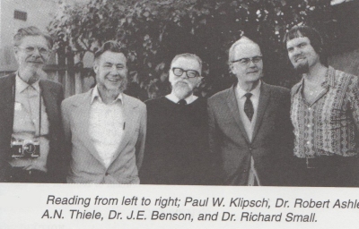
- 2003 co-recipient, with Dr. Richard H Small, of The Institute of Electrical and Electronics Engineers Masaru Ibuka Consumer Electronics Award ‘for major contributions to the synthesis and analysis of loudspeakers’.
- 2003 awarded the Medal of the Order of Australia (OAM) in the 2003 Queen’s Birthday honours ‘for service to audio engineering, particularly in the field of loudspeaker design and the development of audio engineering standards’.
- 2008 Doctor of Science in Architecture (honoris causa)
- 2009 awarded the Peter Barnett Memorial Award by The Institute of Acoustics (U.K.) ‘for technical excellence, practical advancement and education in the fields of electroacoustics and speech intelligibility’.
Publications
- Thiele, A. Neville (1956). "The Design of Filters Using Only RC Sections and Gain Stages," Electronic Engineering, 28(335 & 336), pp. 31-36 & 80-82.
- Thiele, A. Neville (1958). "Television IF Amplifiers with Linear Phase Response," Proceedings of the Institute of Radio Engineers, Australia, 19(11), pp.652-668.
- Thiele, A. Neville (1959). "Recovery of Amplifiers After Overload," Proceedings of the Institute of Radio Engineers, Australia, 20(5), pp.257-261.
- Thiele, A. Neville (1960). "Techniques of Delay Equalisation," Proceedings of the Institute of Radio Engineers, Australia, 21(4), pp. 225-241.
- Thiele, A. Neville (1961). "A Hybrid Network for Mixing and Splitting Signals," Proceedings of the Institute of Radio Engineers, Australia, 22(6), pp. 383-387.
- Thiele, A. Neville (1961). "Loudspeakers in Vented Boxes," Proceedings of the Institute of Radio Engineers, Australia, 22(8), pp. 487-508. Reprinted in Journal of the Audio Engineering Society, 1971, 19(5 & 6), pp. 382-392 & 471-483. Reprinted in R.E. Cooke (ed.) Loudspeakers, An Anthology, Vol. 1 - Vol. 25 (1953-1977), Audio Engineering Society, New York, 1978, pp. 181-204. Reprinted in Vented Loudspeakers - An Anthology, Institute of Radio and Electronics Engineers. Reprinted in German as "Lautsprecher in ventilierten Gehäusen (Die Berechtnungsunterlagen für Baßreflexgehäuse)," Hifiboxen Selbstgemacht, Elrad extra 8, Verlag Heinz Heise GmbH & Co. KG, Hannover, 1989, pp. 91 - 112.
- Thiele, A. Neville (1962). "Equalisation of Gramophone Pickups," Proceedings of the Institute of Radio Engineers, Australia, 23(5), pp. 311-313.
- Thiele, A. Neville (1962). "Miller Resistance," Proceedings of the Institute of Radio Engineers, Australia, 23(6), pp. 359-360.
- Thiele, A. Neville (1965). "Measurement of Return Loss at Video Frequencies," Proceedings of the Institute of Radio and Electronics Engineers, 26(6), pp. 183-191.
- Thiele, A. Neville (1965). "The Theory of Null Traps," Proceedings of the Institute of Radio and Electronics Engineers, 26(7), pp. 224-231.
- Thiele, A. Neville (1965). "Filters with Variable Cut-Off Frequencies," Proceedings of the Institute of Radio and Electronics Engineers, 26(9), pp. 284-301.
- Thiele, A. Neville (1966). "Methods of Waveform (Pulse and Bar) Testing," Proceedings of the Institute of Radio and Electronics Engineers, 27(12), pp. 339-362.
- Thiele, A. Neville (1967). "A Simple Shunt Regulator," Proceedings of the Institute of Radio and Electronics Engineers, 28(5), pp. 175-178.
- Thiele, A. Neville (1967). "Variable Equalisers for Short Video Cables," Proceedings of the Institute of Radio and Electronics Engineers, 28(7), pp. 215-231.
- Thiele, A. Neville and McKilligan, R.S. (1968). "Elimination of Brightness Variation in Television Monitors Appearing "On-Camera"," Proceedings of the Institute of Radio and Electronics Engineers, 29(2), pp. 53-54.
- Thiele, A. Neville (1969). "Horizontal Aperture Equalisation," Proceedings of the Institute of Radio and Electronics Engineers, 30(11), pp. 348-363. Reprinted Radio and Electronic Engineer, 1970.
- Thiele, A. Neville (1970). "Complementary Emitter Follower for Feeding Matched Loads," Proceedings of the Institute of Radio and Electronics Engineers, 31(10), pp. 354-355.
- Thiele, A. Neville (1973). "Loudspeakers, Enclosures and Equalisers," Proceedings of the Institute of Radio and Electronics Engineers, 34(11), pp. 425-448. Reprinted in Vented Loudspeakers - An Anthology, Institute of Radio and Electronics Engineers.
- Thiele, A. Neville (1974). "Inter-Order Response Characteristics for Simplified Active Filters," Proceedings of the Institute of Radio and Electronics Engineers, 35(3), pp. 57-60.
- Thiele, A. Neville (1975). "Optimum Passive Loudspeaker Dividing Networks," Proceedings of the Institute of Radio and Electronics Engineers, 36(7), pp. 220-224.
- Thiele, A. Neville (1975). "Load Stabilising Networks for Audio Amplifiers," Proceedings of the Institute of Radio and Electronics Engineers, 36(9), pp. 297-300. Reprinted Journal of the Audio Engineering Society, 1976, 24(1), pp. 20-23.
- Thiele, A. Neville (1975). "Air-Cored Inductors for Audio," Proceedings of the Institute of Radio and Electronics Engineers Australia, 36(10), pp. 329-333. Reprinted Journal of the Audio Engineering Society, 1976, 24(5), pp. 374-378. Postscript Journal of the Audio Engineering Society, 1976, 24(10), pp. 830-832.
- Thiele, A. Neville (1979). "The Importance of Standards in Broadcasting," The Radio and Electronic Engineer, 49(9), pp. 443-447.
- Thiele, A. Neville (1983). "Measurement of Non-Linear Distortion in a Band-Limited System," Journal of the Audio Engineering Society, 31(6), pp. 443-445.
- Thiele, A. Neville (1985). "Three-Level Tone Test Signal for Setting Audio Levels," Journal of the Audio Engineering Society, 33(12), pp. 963-967; and letter Journal of the Audio Engineering Society, 1986, 34(12), pp.997-998.
- Thiele, A. Neville (1989). "The Decibel in Sound Program Transmission," Journal of Electrical and Electronics Engineering, Australia, 9(1/2), pp. 1-10.
- Thiele, A. Neville (1989). "An Improved Pre-Emphasis Standard for AM Broadcasting," Journal of the Audio Engineering Society, 37(11), pp. 934-939. Reprinted Journal of Electrical and Electronics Engineering, Australia, 1990, 10(1), pp.12-19.
- Thiele, A. Neville (1989). "Measurement of the Thiele-Small Parameters of Tweeters," Journal of Electrical and Electronics Engineering, Australia, 9(4), pp. 186-199.
- Thiele, A. Neville (1992). "An Improved Law of Contrast Gradient for High Definition Television," Journal of Electrical and Electronics Engineering, Australia, 12(4), pp. 394-402. Reprinted Journal of the Society of Motion Picture and Television Engineers, 1992, 103(1), pp. 18-25.
- Thiele, A. Neville (1993). "Force Conversion Factors of a Loudspeaker Driver," Journal of Electrical and Electronics Engineering, Australia, 13(2), pp. 129-131. Reprinted Journal of the Audio Engineering Society, 1993, 41(9), pp. 701-703.
- Thiele, A. Neville and Burton, John (1993). "Standards in Digital Video," Journal of Electrical and Electronics Engineering, Australia, 13(3), pp. 133-139.
- Thiele, A. Neville (1993). "Research and Development in Digital Video and Multimedia in Australia," Journal of Electrical and Electronics Engineering, Australia, 13(3), pp. 140-152.
- Thiele, A. Neville (1993). "Digital Audio for Digital Video," Journal of Electrical and Electronics Engineering, Australia, 13(3), pp. 246-256.
- Thiele, A. Neville (1997). "Precise Passive Crossovers incorporating Loudspeaker Driver Parameters," Journal of the Audio Engineering Society, 45(7/8), pp. 585-594.
- Thiele, A. Neville (2000). "Loudspeaker Crossovers with Notched Responses," Journal of the Audio Engineering Society, 48(9), pp. 786-799.
- Thiele, A. Neville (2000). "An Air-Cored Autotransformer with Nearly Equal Decibel Taps," Journal of the Audio Engineering Society, 48(12), pp. 1194-1215.
- Thiele, A. Neville (2002). "Estimating Loudspeaker Response when the Vent Output is Delayed," Journal of the Audio Engineering Society, 50(3), pp. 173-175.
- Thiele, A. Neville (2002). "A Passive Crossover System of Order 3(Low-Pass) + 5(High-Pass) Incorporating Driver Parameters," Journal of the Audio Engineering Society, 50(12), pp. 1030-1038.
- Thiele, A. Neville (2007). "Implementing Asymmetrical Crossovers," Journal of the Audio Engineering Society, 55(10), pp. 819-832.
- Thiele, A. Neville (2010). "Closed Box Loudspeaker with a Series Capacitor," Journal of the Audio Engineering Society, 58(7/8), pp. 577-582.
Richard H. Small
Richard H. Small (born 1935) is an American scientist, who worked mainly on electroacoustics. The Thiele/Small parameters are named after him and Neville Thiele.
Career
Small was born in San Diego, California.
His father was an amateur pianist. Having a keen interest in
electronics he built the amplifiers to drive the speakers in his parents
house. His father built various enclosures for the loudspeakers,
following the trends of the times. He earned a Bachelor of Science
degree from the California Institute of Technology in 1956 and a Master of Science degree in electrical engineering from the Massachusetts Institute of Technology in 1958. He gained experience in electronic circuit design for high-performance analytical instruments at the Bell & Howell
Research Center in California from 1958 to 1964. During this period, he
took a one-year visiting fellowship at the Norwegian Technical
University. After a working visit to Japan in 1964, he moved to
Australia, where he got a part-time job at the University of Sydney as a teaching assistant in the electronics lab. He became interested in loudspeaker analysis and measurement and met A. N. Thiele
who was lecturing at the university. He was awarded a Ph.D. degree in
1972. Upon completion of his Ph.D., he published a series of nine
papers—now considered classics—on the low-frequency analysis of
closed-box, vented and passive radiator loudspeaker systems. He taught
for a number of years at that university, but returned to industry in
1986 as Head of Research at KEF Electronics Ltd. in Maidstone, England until 1993. He then joined Harman International based in their Martinsville, Indiana, USA facility.
Thiele/Small
"Thiele/Small" commonly refers to a set of electromechanical parameters that define the specified low frequency performance of a loudspeaker driver. These parameters are published in specification sheets by driver manufacturers so that designers have a guide in selecting off-the-shelf drivers for loudspeaker designs. Using these parameters, a loudspeaker designer may simulate the position, velocity and acceleration of the diaphragm, the input impedance and the sound output of a system comprising a loudspeaker and enclosure. Many of the parameters are strictly defined only at the resonant frequency, but the approach is generally applicable in the frequency range where the diaphragm motion is largely pistonic, i.e. when the entire cone moves in and out as a unit without cone breakup.
Rather than purchase off-the-shelf components, loudspeaker design engineers often define desired performance and work backwards to a set of parameters and manufacture a driver with said characteristics or order it from a driver manufacturer. This process of generating parameters from a target response is known as synthesis. Thiele/Small parameters are named after A. Neville Thiele of the Australian Broadcasting Commission, and Richard H. Small of the University of Sydney, who pioneered this line of analysis for loudspeakers.
History
The 1925 paper of Chester W. Rice and Edward W. Kellogg, fueled by advances in radio and electronics, increased interest in direct radiator loudspeakers. In 1930, A. J. Thuras of Bell Labs patented (US Patent No. 1869178) his "Sound Translating Device" (essentially a vented box) which was evidence of the interest in many types of enclosure design at the time.
Progress on loudspeaker enclosure design and analysis using acoustic analogous circuits by academic acousticians like Harry F. Olson continued until 1954 when Leo L. Beranek of the Massachusetts Institute of Technology published Acoustics,[1] a book summarizing and extending the electroacoustics of the era. J. F. Novak used novel simplifying assumptions in an analysis in a 1959 paper which led to a practical solution for the response of a given loudspeaker in a box, and also established their applicability by empirical measurement. In 1961, leaning heavily on Novak's work, A. N. Thiele described a series of sealed and vented box "alignments" (i.e., enclosure designs based on electrical filter theory with well-characterized behavior, including frequency response, power handling, cone excursion, etc.) in a publication in an Australian journal.[2] This paper remained relatively unknown outside Australia until it was re-published in the Journal of the Audio Engineering Society in 1971. It is important to note that Thiele's work neglected enclosure losses and, though a breakthrough at the time, his alignment tables now have little real-world utility.
Many others continued to develop various aspects of loudspeaker enclosure design in the 1960s and early 1970s. From 1968-1972 J. E. Benson published three articles in an Australian journal that thoroughly analyzed sealed, vented and passive radiator designs, all using the same basic model. Beginning June 1972, Richard H. Small published a series of very influential articles in the Journal of the Audio Engineering Society restating and extending Thiele's work. These articles were also originally published in Australia, where he had attended graduate school, and where his thesis supervisor was J.E. Benson. The work of Benson and Small overlapped considerably, but differed in that Benson did his work using computer programs and Small used analog simulators. Both researchers analyzed the systems including enclosure losses.
Fundamental small signal mechanical parameters
These are the physical parameters of a loudspeaker driver, as measured at small signal levels, used in the equivalent electrical circuit models. Some of these values are neither easy nor convenient to measure in a finished loudspeaker driver, so when designing speakers using existing drive units (which is almost always the case), the more easily measured parameters listed under Small Signal Parameters are more practical.
- Sd - Projected area of the driver diaphragm, in square metres.
- Mms - Mass of the diaphragm/coil, including acoustic load, in kilograms. Mass of the diaphragm/coil alone is known as Mmd
- Cms - Compliance of the driver's suspension, in metres per newton (the reciprocal of its 'stiffness').
- Rms - The mechanical resistance of a driver's suspension (i.e., 'lossiness') in N·s/m
- Le - Voice coil inductance measured in millihenries (mH) (Frequency dependent, usually measured at 1 kHz).
- Re - DC resistance of the voice coil, measured in ohms.
- Bl - The product of magnet field strength in the voice coil gap and the length of wire in the magnetic field, in tesla-metres (T·m).
Small signal parameters
These values can be determined by measuring the input impedance of the driver, near the resonance frequency, at small input levels for which the mechanical behavior of the driver is effectively linear (i.e., proportional to its input). These values are more easily measured than the fundamental ones above.
- Fs – Resonance frequency of the driver
- Qes – Electrical Q of the driver at Fs
- Qms – Mechanical Q of the driver at Fs
- Qts – Total Q of the driver at Fs
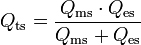
- Vas – Equivalent Compliance Volume, i.e. the volume of air which, when acted upon by a piston of area Sd, has the same compliance as the driver's suspension:
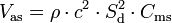
- where ρ is the density of air (1.184 kg/m3 at 25 °C), and c is the speed of sound (346.1 m/s at 25 °C). Using SI units, the result will be in cubic meters. To get Vas in litres, multiply by 1000.
Large signal parameters
These parameters are useful for predicting the approximate output of a driver at high input levels, though they are harder to accurately measure.
- Xmax - Maximum linear peak (or sometimes peak-to-peak) excursion (in mm) of the cone. Note that, because of mechanical issues, the motion of a driver cone becomes non-linear with large excursions, especially those in excess of this parameter.
- Xmech - Maximum physical excursion of the driver before physical damage. With a sufficiently large input, the excursion will cause damage to the voice coil or other moving part of the driver.
- Pe - Thermal power handling capacity of the driver, in watts. This value is difficult to characterize and is often overestimated, by manufacturers and others.
- Vd - Peak displacement volume, calculated by Vd = Sd·Xmax
Other parameters
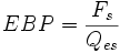
- Zmax - The impedance of the driver at Fs, used when measuring Qes and Qms.

- EBP - The efficiency bandwidth product, a rough indicator measure. A common rule of thumb indicates that for EBP>100, a driver is perhaps best used in a vented enclosure, while EBP<50 indicates a sealed enclosure. For 50<EBP<100, either enclosure may be used effectively.
- Znom - The nominal impedance of the loudspeaker, typically 4, 8 or 16 ohms.
- η0 - The reference or "power available" efficiency of the driver, in percent.
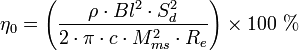
- The expression ρ/2πc can be replaced by the value 5.445×10⁻⁴ m²·s/kg for dry air at 25 °C. For 25 °C air with 50% relative humidity the expression evaluates to 5.365×10⁻⁴ m²·s/kg.
- A version more easily calculated with typical published parameters is:
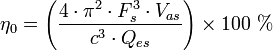
- The expression 4π2/c3 can be replaced by the value 9.523×10⁻⁷ s³/m³ for dry air at 25 °C. For 25 °C air with 50% relative humidity the expression evaluates to 9.438×10⁻⁷ s³/m³.
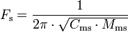
- From the efficiency, we may calculate sensitivity, which is the sound pressure level a speaker produces for a given input:
- A speaker with an efficiency of 100% (1.0) would output a watt of energy for every watt of input. Considering the driver as a point source in an infinite baffle, at one meter this would be distributed over a hemisphere with area 2π m² for an intensity of (1/(2π))=0.159154 W/m², which gives an SPL of 112.1 dB in reference to the reference pressure of 2e-5 Pascals.
- SPL at 1 meter for an input of 1 watt is then: dB(1 watt) = 112.1 + 10*log(η0)
- SPL at 1 meter for an input of 2.83 volts is then: dB(2.83 V) = dB(1 watt) + 10*log(8/Re) = 112.1 + 10*log(η0) + 10*log(8/Re)
Qualitative descriptions

- Fs
- Also called F0, resonance frequency measured in hertz (Hz). The frequency at which the combination of the energy stored in the moving mass and suspension compliance is maximum, and results in maximum cone velocity. A more compliant suspension or a larger moving mass will cause a lower resonance frequency, and vice versa. Usually it is less efficient to produce output at frequencies below Fs, and input signals significantly below Fs can cause large excursions, mechanically endangering the driver. Woofers typically have an Fs in the range of 13–60 Hz. Midranges usually have an Fs in the range of 60–500 Hz and tweeters between 500 Hz and 4 kHz. A typical factory tolerance for Fs spec is ±15%.
- Qts
- A unitless measurement, characterizing the combined electric and mechanical damping of the driver. In electronics, Q is the inverse of the damping ratio. The value of Qts is proportional to the energy stored, divided by the energy dissipated, and is defined at resonance (Fs). Most drivers have Qts values between 0.2 and 0.5, but there are valid (if unusual) reasons to have a value outside this range.
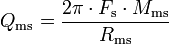
- Qms
- A unitless measurement, characterizing the mechanical damping of the driver, that is, the losses in the suspension (surround and spider.) It varies roughly between 0.5 and 10, with a typical value around 3. High Qms indicates lower mechanical losses, and low Qms indicates higher losses. The main effect of Qms is on the impedance of the driver, with high Qms drivers displaying a higher impedance peak. One predictor for low Qms is a metallic voice coil former. These act as eddy-current brakes and increase damping, reducing Qms. They must be designed with an electrical break in the cylinder (so no conducting loop). Some speaker manufacturers have placed shorted turns at the top and bottom of the voice coil to prevent it leaving the gap, but the sharp noise created by this device when the driver is overdriven is alarming and was perceived as a problem by owners. High Qms drivers are often built with nonconductive formers, made from paper, or various plastics.
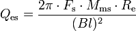
- Qes
- A unitless measurement, describing the electrical damping of the loudspeaker. As the coil of wire moves through the magnetic field, it generates a current which opposes the motion of the coil. This so-called "Back-EMF" (proportional to Bl * velocity) decreases the total current through the coil near the resonance frequency, reducing cone movement and increasing impedance. In most drivers, Qes is the dominant factor in the voice coil damping. Qes depends on amplifier output impedance. The formula above assumes zero output impedance. When an amplifier with nonzero output impedance is used, its output impedance should be added to Re for calculations involving Qes.
- Bl
- Measured in tesla-metres (T·m). Technically this is B×l or B×l sin(θ) (a vector cross product), but the standard geometry of a circular coil in an annular voice coil gap gives sin(θ)=1. B×l is also known as the 'force factor' because the force on the coil imposed by the magnet is B×l multiplied by the current through the coil. The higher the B×l value, the larger the force generated by a given current flowing through the voice coil. B×l has a very strong effect on Qes.
- Vas
- Measured in litres (L) or cubic metres, is a measure of the 'stiffness' of the suspension with the driver mounted in free air. It represents the volume of air that has the same stiffness as the driver's suspension when acted on by a piston of the same area (Sd) as the cone. Larger values mean lower stiffness, and generally require larger enclosures. Vas varies with the square of the diameter. A typical factory tolerance for Vas spec is ±20–30%.
- Mms
- Measured in grams (g) or kilograms (kg), this is the mass of the cone, coil and other moving parts of a driver, including the acoustic load imposed by the air in contact with the driver cone. Mmd is the cone/coil mass without the acoustic load, and the two should not be confused. Some simulation software calculates Mms when Mmd is entered. Mmd can be very closely controlled by the manufacturer.
- Rms
- Units are not usually given for this parameter, but it is in mechanical 'ohms'. Rms is a measurement of the losses, or damping, in a driver's suspension and moving system. It is the main factor in determining Qms. Rms is influenced by suspension topology, materials, and by the voice coil former (bobbin) material.
- Cms
- Measured in metres per newton (m/N). Describes the compliance (ie, the inverse of stiffness) of the suspension. The more compliant a suspension system is, the lower its stiffness, so the higher the Vas will be. Cms is proportional to Vas and thus has the same tolerance ranges.
- Re
- Measured in ohms (Ω), this is the DC resistance (DCR) of the voice coil, best measured with the cone blocked, or prevented from moving or vibrating because otherwise the pickup of ambient sounds can cause the measurement to be unreliable. Re should not be confused with the rated driver impedance, Re can be tightly controlled by the manufacturer, while rated impedance values are often approximate at best.. American EIA standard RS-299A specifies that Re (or DCR) should be at least 80% of the rated driver impedance, so an 8-ohm rated driver should have a DC resistance of at least 6.4 ohms, and a 4-ohm unit should measure 3.2 ohms minimum. This standard is voluntary, and many 8 ohm drivers have resistances of ~5.5 ohms, and proportionally lower for lower rated impedances.
- Le
- Measured in millihenries (mH), this is the inductance of the voice coil. The coil is a lossy inductor, in part due to losses in the pole piece, so the apparent inductance changes with frequency. Large Le values limit the high frequency output of the driver and cause response changes near cutoff. Simple modeling software often neglects Le, and so does not include its consequences. Inductance varies with excursion because the voice coil moves relative to the polepiece, which acts as a sliding inductor core, increasing inductance on the inward stroke and decreasing it on the outward stroke in typical overhung coil arrangements. This inductance modulation is an important source of nonlinearity (distortion) in loudspeakers. Including a copper cap on the pole piece, or a copper shorting ring on it, can reduce the increase in impedance seen at higher frequencies in typical drivers, and also reduce the nonlinearity due to inductance modulation.
- Sd
- Measured in square metres (m²). The effective projected area of the cone or diaphragm. It is difficult to measure and depends largely on the shape and properties of the surround. Generally accepted as the cone body diameter plus one third to one half the width of the annulus (surround). Drivers with wide roll surrounds can have significantly less Sd than conventional types with the same frame diameter.
- Xmax
- Specified in millimeters (mm). In the simplest form, subtract the height of the voice coil winding from the height of the magnetic gap, take the absolute value and divide by 2. This technique was suggested by JBL's Mark Gander in a 1981 AES paper, as an indicator of a loudspeaker motor's linear range. Although easily determined, it neglects magnetic and mechanical non-linearities and asymmetry, which are substantial for some drivers. Subsequently, a combined mechanical/acoustical measure was suggested, in which a driver is progressively driven to high levels at low frequencies, with Xmax determined by measuring excursion at a level where 10% THD is measured in the output. This method better represents actual driver performance, but is more difficult and time-consuming to determine.
- Pe
- Specified in watts. Frequently two power ratings are given, an "RMS" rating and a "music" (or "peak", or "system") rating, usually peak is given as ~2 times the RMS rating. Loudspeakers have complex behavior, and a single number is really unsatisfactory. There are two aspects of power handling, thermal and mechanical. The thermal capacity is related to coil temperature and the point where adhesives and coil insulation melt or change shape. The mechanical limit comes into play at low frequencies, where excursions are largest, and involves mechanical failure of some component. A speaker that can handle 200 watts thermally at 200Hz, may sometimes be damaged by only a few watts at some very low frequency, like 10Hz. Power handling specifications are usually generated destructively, by long term industry standard noise signals (IEC 268, for example) that filter out low frequencies and test only the thermal capability of the driver. Actual mechanical power handling depends greatly on the enclosure in which the driver is installed.
- Vd
- Specified in litres (L). The volume displaced by the cone, equal to the cone area (Sd) multiplied by Xmax. A particular value may be achieved in any of several ways. For instance, by having a small cone with a large Xmax, or a large cone with a small Xmax. Comparing Vd values will give an indication of the maximum output of a driver at low frequencies. High Xmax, small cone diameter drivers are likely to be inefficient, since much of the voice coil winding will be outside the magnetic gap at any one time and will therefore contribute little or nothing to cone motion. Likewise, large cone diameter, small Xmax drivers are likely to be more efficient as they will not need, and so may not have, long voice coils.
- η0 - Reference Efficiency
- Specified in percent (%). Comparing drivers by their calculated reference efficiency is often more useful than using 'sensitivity' since manufacturer sensitivity figures are too often optimistic.
- Sensitivity
- The sound pressure, in dB, produced by a speaker in response to a specified stimulus. Usually this is specified at an input of 1 watt or 2.83 volts (2.83 volts = 1 watt into an 8 ohm load) at a distance of one metre.
Measurement notes—large signal behavior
Some caution is required when using and interpreting T/S parameters. It is important to mention that individual units may not match manufacturer specifications. Parameters values are almost never individually taken, but are at best averages across a production run, due to inevitable manufacturing variations. Driver characteristics will generally lie within a (sometimes specified) tolerance range. Cms is the least controllable parameter, but typical variations in Cms do not have large effects on the final response.[3]
It is also important to understand that most T/S parameters are linearized small signal values. An analysis based on them is an idealized view of driver behavior, since the actual values of these parameters vary in all drivers according to drive level, voice coil temperature, over the life of the driver, etc. Cms decreases the farther the coil moves from rest. Bl is generally maximum at rest, and drops as the voice coil approaches Xmax. Re increases as the coil heats and the value will typically double by 270 °C (exactly 266 °C for Cu and 254 °C for Al), at which many voice coils are approaching (or have already reached) thermal failure.
As an example, Fs and Vas may vary considerably with input level, due to nonlinear changes in Cms. A typical 110 mm diameter full-range driver with an Fs of 95 Hz at 0.5 V signal level, might drop to 64 Hz when fed a 5 V input. A driver with a measured Vas of 7 L at 0.5 V, may show a Vas increase to 13 L when tested at 4 V. Qms is typically stable within a few percent, regardless of drive level. Qes and Qts decrease <13% as the drive level rises from 0.5 V to 4 V, due to the changes in Bl. Because Vas can rise significantly and Fs can drop considerably, with a trivial change in measured Mms, the calculated sensitivity value (η0) can appear to drop by >30% as the level changes from 0.5 V to 4 V. Of course, the driver's actual sensitivity has not changed at all, but the calculated sensitivity is correct only under some conditions. From this example, it is seen that the measurements to be preferred while designing an enclosure or system are those likely to represent typical operating conditions. Unfortunately, this level must be arbitrary, since the operating conditions are continually changing when reproducing music. Level-dependent nonlinearities typically cause lower than predicted output, or small variations in frequency response.
Level shifts caused by resistive heating of the voice coil are termed power compression. Design techniques which reduce nonlinearities may also reduce power compression, and possibly distortions not caused by power compression. There have been several commercial designs that have included cooling arrangements for driver magnetic structures, intended to mitigate voice coil temperature rise, and the attendant rise in resistance that is the cause of the power compression. Elegant magnet and coil designs have been used to linearize Bl and reduce the value and modulation of Le. Large, linear spiders can increase the linear range of Cms, but the large signal values of Bl and Cms must be balanced to avoid dynamic offset.
Lifetime changes in driver behavior
The mechanical components in typical speaker drivers may change over time. Paper, a popular material in cone fabrication, absorbs moisture easily and unless treated may lose some structural rigidity over time. This may be reduced by coating with water-impregnable material such as various plastic resins. Cracks compromise structural rigidity and if large enough are generally non-repairable. Temperature has a strong, generally reversible effect; typical suspension materials become stiffer at lower temperatures. The suspension also undergoes changes from chemical and environmental effects associated with aging such as exposure to ultraviolet light, and oxidation which affect foam and natural rubber components badly, though butyl, nitrile, SBR rubber, and rubber-plastic alloys (such as Santoprene) are more stable. Foam is highly prone to disintegration after 10 to 15 years. The changes in behavior from aging are rarely positive, and since the environment that they are used in is a major factor, the effects are not easily predicted. Gilbert Briggs, founder of Wharfedale Loudspeakers in the UK, undertook several studies of aging effects in speaker drivers in the 1950s and 1960s, publishing some of the data in his books, notably Loudspeakers.
There are also mechanical changes which occur in the moving components during use. In this case, however, most of the changes seem to occur early in the life of the driver, and are almost certainly due to relaxation in flexing mechanical parts of the driver (e.g., surround, spider, etc.). Several studies have been published documenting substantial changes in the T/S parameters over the first few hours of use, some parameters changing as much as 15%+ over these initial periods. The proprietor of GR research as publicly reported several such investigations of several manufacturers' drivers. Other studies suggest little change, or reversible changes after only the first few minutes. This variability is largely related to the particular characteristics of specific materials, and reputable manufacturers attempt to take them into account. While there are a great many anecdotal reports of the audible effects of such changes in published speaker reviews, the relationship of such early changes to subjective sound quality reports is not completely clear. Some changes early in driver life are complementary (such as a reduction in Fs accompanied by a rise in Vas) and result in minimal net changes (small fractions of a dB) in frequency response. If the performance of speaker system is critical, as with high order (complex) or heavily equalized systems, it is sensible to measure T/S parameters after a period of run-in (some hours, typically, using program material), and to model the effects of normal parameter changes on driver performance.
Measurement techniques
There are numerous methods to measure T/S parameters, but the simplest use the input impedance of the driver, measured near resonance. The impedance may be measured in free air (with the driver unhoused and either clamped to a fixture or hanging from a wire, or sometimes resting on the magnet on a surface) and/or in test baffles, sealed or vented boxes or with varying amounts of mass added to the diaphragm. Noise in the measurement environment can have an effect on the measurement, so one should measure parameters in a quiet acoustic environment.
The most common (DIY-friendly) method before the advent of computer-controlled measurement techniques is the classic free air constant current method, described by Thiele in 1961. This method uses a large resistance (e.g., 500 to 1000 ohms) in series with the driver and a signal generator is used to vary the excitation frequency. The voltage across the loudspeaker terminals is measured and considered proportional to the impedance. It is assumed that variations in loudspeaker impedance will have little effect on the current through the loudspeaker. This is an approximation, and the method results in Q measurement errors for drivers with a high Zmax.
A second method is the constant voltage measurement, where the driver is excited by a constant voltage, and the current passing through the coil is measured. The excitation voltage divided by the measured current equals the impedance.
A common source of error using these first two methods is the use of inexpensive AC meters. Most inexpensive meters are designed to measure residential power frequencies (50–60 Hz) and are increasingly inaccurate at other frequencies (e.g., below 40 Hz or above a few hundred hertz). In addition, distorted or non–sine wave signals can cause measurement inaccuracies. Inexpensive voltmeters are also not very accurate or precise at measuring current and can introduce appreciable series resistance, which causes measurement errors.
A third method is a response to the deficiencies of the first two methods. It uses a smaller (e.g., 10 ohm) series resistor and measurements are made of the voltage across the driver, the signal generator, and/or series resistor for frequencies around resonance. Although tedious, and not often used in manual measurements, simple calculations exist which allow the true impedance magnitude and phase to be determined. This is the method used by many computer loudspeaker measurement systems. When this method is used manually, the result of taking the three measurements is that their ratios are more important than their actual value, removing the effect of poor meter frequency response